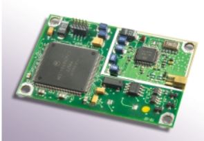
 The M12+ Oncore receiver is capable of tracking twelve satellites simultaneously. The module receives the L1 GPS signal (1575.42 MHz) from the antenna and operates off the coarse/acquisition (C/A) code tracking. The code tracking is carrier aided. Time recovery capability is inherent in the architecture.
The L1 band signals transmitted from GPS satellites are typically collected, filtered, and amplified by microstrip patch antennas such as the Motorola Hawk or Timing 2000. Signals from the antenna module are then routed to the RF signal processing section of the M12+ via a single coaxial interconnecting cable. This interconnecting cable also provides bias power for the low-noise-amplifier (LNA) in the antenna. The M12+ is capable of providing the antenna with voltages from 2.5-5.5V at currents up to 80mA.
The RF signal processing section of the M12+ printed circuit board (PCB) contains the required circuitry for down-converting the GPS signals received from the antenna module. The resulting intermediate frequency (IF) signal is then passed to the twelve channel code and carrier correlator section of the M12+ where a single, high speed analog-to-digital (A/D) converter converts the IF signal to a digital sequence prior to channel separation. This digitized IF signal is then routed to the digital signal processor where the signal is split into twelve parallel channels for signal detection, code correlation, carrier tracking, and filtering.
The processed signals are synchronously routed to the position microprocessor (MPU) section. This section controls the receiver operating modes, decodes and processes satellite data, and the pseudo-range and delta range measurements used to compute position, velocity, and time. In addition, the position processor section contains the inverted serial interface.
M12+ Receiver Electrical Connections
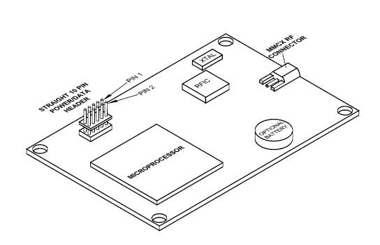
The M12+ receivers receive electrical power and receive/transmit I/O signals through a 10-pin power/data connector mounted on the receiver. Figure below illustrates the positions of both the 10-pin header and the MMCX antenna connector.

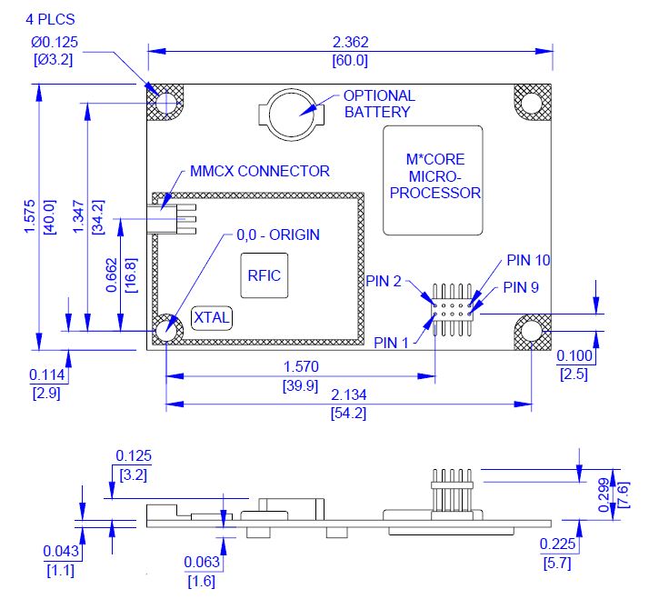
M12+ ONCORE RECEIVER PRINTED CIRCUIT BOARD MECHANICAL DRAWINGS
Use this drawing to identify the M12+ OnCore Receiver.

